Automotive wiring harness connectors are used to connect various connection points of automotive circuits. They are important parts of the car, and their quality directly affects the transmission effect of power or signals.
The connector accounts for a small proportion of the cost of the car, but if there are quality problems in the use of the car, it often has serious consequences and the maintenance cost increases significantly. Therefore, the quality of the connector is increasingly valued by automakers and parts suppliers.
Terminal withdrawal is a common failure form of automotive wiring harness connectors. It means that after the connector is assembled, the terminal and the sheath are abnormally separated, resulting in the loss of the connector function.
The causes of this failure form generally include three aspects:
① The retention force of the terminal in the sheath is unqualified;
② Interference with insertion;
③ Product application problems.
This article analyzes the withdrawal of connector terminals based on these three reasons and proposes solutions.
The retention force of the terminal in the sheath is unqualified
The retention force of the terminal in the sheath refers to the force required to separate the terminal from the sheath in the axial direction.
In order to avoid the phenomenon of terminal withdrawal, the performance test standard of the connector has strict regulations on the retention force of the terminal in the sheath:
① The retention force of the connector with a specification not greater than 2.8 is greater than 40N;
② The retention force of the connector with a specification greater than 2.8 is greater than 60N. In practice, many terminal withdrawal phenomena are caused by the retention force not meeting the regulations.
Generally speaking, the reasons for the unqualified retention force of the terminal in the sheath are:
- Structural design problems;
- Material selection problems.
Structural Design Issues
The structural design issues of the connector involving the terminal retention force mainly refer to the design of the hanging structure of the terminal and the sheath.
This hanging structure is generally an elastic structure, which is divided into an elastic structure on the sheath and an elastic structure on the terminal.
Elastic Structure On The Sheath
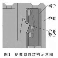
The elastic structure of the sheath is shown in Figure 1.
The elastic structure on the sheath means that the elastic structure required for the assembly of the terminal and the sheath is designed on the sheath. During the assembly process of the terminal and the sheath, the sheath spring tongue (elastic structure designed on the sheath) is deformed by force to achieve the assembly of the terminal and the sheath.
After the terminal and the sheath are assembled in place, the sheath spring tongue returns to its original state due to the release of force.
The cooperation between the sheath spring tongue and the hanging platform structure designed on the terminal ensures the effective positioning of the sheath on the terminal.
The shear strength of the sheath spring tongue determines the retention force of the terminal in the sheath. The shear stress calculation formula is as follows

Where: τ——— shear stress on the material; F——— force in the shear direction of the material; A——— shear area; [τ]— allowable yield shear stress of the material.
From formula (1), it can be seen that the maximum force on the material in the shear direction is proportional to the shear area of the material and the allowable shear stress of the material.
When designing the spring tongue of the sheath, once the material is selected, the allowable yield shear stress of the material is fixed. To ensure that the product meets the retention force requirements of the terminal in the sheath (force in the shear direction), it is necessary to ensure that the shear area of the spring tongue of the sheath meets the required value.
In practice, due to the design gap between the terminal and the sheath, the shear area should be calculated according to the extreme worst case.
The design gap between the terminal and the sheath should ensure that the yield shear stress that the shear area can withstand under the extreme worst case is greater than the required retention force of the terminal in the sheath.
The elastic structure is used on the terminal.
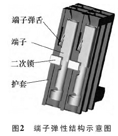
The elastic structure of the terminal is shown in Figure 2.
The elastic structure used on the terminal means that the elastic structure required for the assembly of the terminal and the sleeve is designed on the terminal.
During the assembly process of the terminal and the sleeve, the terminal spring tongue (elastic structure designed on the terminal) is deformed by force to achieve the assembly of the terminal and the sleeve.
After the terminal and the sleeve are assembled in place, the terminal spring tongue returns to its original state due to the release of force.
The cooperation between the terminal spring tongue and the hanging platform structure designed on the sleeve ensures the effective positioning of the sleeve on the terminal.
The yield strength of the terminal spring tongue determines the holding force of the terminal in the sleeve.
It can be seen from formula (1) that when designing the terminal spring tongue, once the material is selected, the allowable shear stress of the material is fixed.
To ensure that the product meets the holding force (stress in the shear direction) requirements of the terminal in the sleeve, it is necessary to ensure that the shear area of the terminal spring tongue meets the required value.
In practice, due to the design gap between the terminal and the sheath, in addition to considering the shear area of the terminal spring tongue (material thickness and spring tongue width), it should be ensured that under extremely harsh conditions, the terminal spring tongue and the hanging platform structure designed on the sheath have a complete fit.
Material Selection Issues
Sheath Material Selection
Common materials for connector sheaths include: polyamide (commonly known as nylon), polybutylene terephthalate (PBT), ABS, etc. For the sheath spring tongue structure, the toughness of the material is generally considered, and the size of the spring tongue structure is designed according to the allowable yield shear stress of the material that meets the toughness requirements.
It should be emphasized that the allowable yield shear stress of the material should be calculated according to the allowable value after the material is subjected to the high temperature aging, temperature-humidity cycle, chemical liquid corrosion and other tests that may exist in the connector.
If the spring tongue structure designed according to the allowable yield shear stress value after the test cannot meet the requirements, it should be considered to replace the material or use a secondary lock structure (Figure 2) to solve it.
When the initial retention force of the connector is normal, and the retention force after the test is unqualified and the needle is withdrawn, it is generally because the spring tongue structure is designed according to the initial allowable yield shear stress of the material used.
Terminal Material Selection
Common materials for connector terminals are: copper, brass, and bronze. According to their hardness, they can be divided into three states: soft, semi-hard, and hard.
Among these three materials, copper is less used and is generally used for grounding holes or fork connectors. Brass and bronze are more commonly used.
Brass has better conductivity than bronze, while bronze has better hardness and elasticity than brass.
When using a terminal tongue structure, bronze should generally be used. The use of brass materials often results in insufficient retention.
Terminal Interference
Terminal interference refers to the failure of the connector during the plug-in process, in which the male terminal is inserted into the non-effective area of the female terminal, causing the connector to lose its function such as the pin withdrawal.
Generally speaking, the causes of terminal interference are:
- structural design problems;
- terminal plug-in force problems.
Structural Design Issues
The main structural design issues of connectors involving terminal interference are: the center distance design of the connector (including dimensional errors or excessive tolerances), the clearance design of the terminal and the sheath (including excessive or too small clearances), etc.
When there are problems with the structural design, the male and female terminals will be misaligned during the plug-in process of the connector.
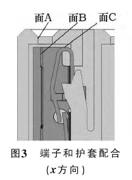
When this misalignment occurs in the x direction (Figure 3), the male terminal will be pressed against the top of surface B or surface C.
If the degree is relatively mild, it will cause the plug-in force of the connector to be too large. If the degree is severe, it will cause the terminal to be withdrawn during the plug-in process.
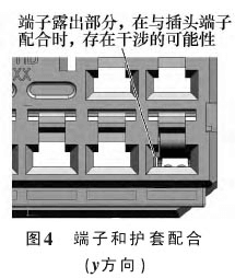
When this misalignment occurs in the y direction (Figure 4), the female terminal will be exposed in an undesirable way, and the male terminal is easy to press against the exposed part of the female terminal.
If the degree is relatively mild, it will cause the plug-in force of the connector to be too large. If the degree is severe, it will cause the terminal to be withdrawn during the plug-in process.
For example, during the assembly process of the fuse box and the wiring harness in the engine compartment of a certain automobile factory, the wiring harness end connector terminals frequently withdrew and the insertion force was large, with a withdrawal rate of 15% and a large insertion force rate of all.
After analyzing the problem parts, it was found that due to the design problem of the center distance of the corresponding fuse box structure that was plugged into the wiring harness end, the male and female terminals were not centered during the plug-in process, resulting in a large insertion force during the assembly of the wiring harness end connector and the fuse box, and the wiring harness end connector terminals partially withdrew.
After improving the design of the corresponding structure of the fuse box, the problem was solved.
Terminal plugging and unplugging force problem
Due to the requirements of assembly performance, the plugging and unplugging force of the connector terminal should be as small as possible.
However, too small a plugging and unplugging force will increase the contact resistance of the connector and reduce its conductivity. Therefore, the appropriate terminal plugging and unplugging force is to meet the requirements of the connector assembly performance under the premise of ensuring the electrical performance of the connector.
In order to improve the conductivity of the terminal, the plugging and unplugging force of the terminal is often increased in practice, which generally leads to assembly difficulties.
When the plugging and unplugging force of the terminal is greater than the holding force of the terminal in the sheath, it may cause the terminal to withdraw during the plugging process of the connector.
Product Application Problems
Product application problems involving the withdrawal of connector terminals mainly refer to problems that may cause the withdrawal of terminals during the production of wiring harnesses.
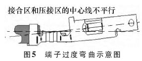
Generally, they include terminal crimping problems and terminal assembly problems. “Banana” terminals are common problems in the terminal crimping process.
It refers to the excessive bending of terminals due to improper crimping, which makes the center lines of the terminal joint area and the crimping area non-parallel, as shown in Figure 5.
When the degree of excessive bending is relatively mild, it will increase the plug-in and pull-out force of the connector and affect the assembly performance;
when the degree is severe, it will cause the male terminal to be unable to be inserted into the effective insertion area of the female terminal during the plug-in process of the connector, thereby causing the terminal to withdraw.
For example, during the plug-in assembly process of the rear taillight and the wiring harness in the general assembly workshop of a certain automobile factory, the wiring harness-end connector terminals frequently withdrew, with an occurrence rate of 20%.
After analyzing the problem parts, it was found that due to improper crimping of the terminals, some terminals were excessively bent (banana terminals), which caused the wiring harness-end connector terminals to withdraw during the assembly process of the wiring harness-end connector and the rear taillight.
After adjusting the terminal crimping, the problem was solved.
The twisting and deformation of the terminal tongue are also common problems in the terminal crimping process.
Severe twisting and deformation will reduce the retention force of the terminal in the sheath and may cause the terminal to withdraw during the plug-in process of the connector.
The assembly process of the terminal and the sheath generally requires “one plug, two listen, and three pull back”.
If it is not assembled according to this requirement, defects such as incomplete terminal assembly may occur, which may also cause the terminal to withdraw during the terminal plug-in process or the semi-finished wire harness circulation process on the production line.
Conclusion
The reasons for the connector terminal to be pulled out include three aspects:
① The retention force of the terminal in the sheath is not up to standard – generally caused by design reasons, manufacturing reasons or the use of materials;
② Insertion interference – generally caused by design reasons or manufacturing reasons;
③ Product application problems – mainly caused by inappropriate use methods during product use.
In actual use, if the terminal is pulled out, the cause of the problem should be analyzed first and solved in a targeted manner.