Standardizes terminal wiring harness manufacturing standards to ensure that products meet quality requirements!
This standard applies to all terminal crimping products.
The production department can produce according to this standard, and the quality department can inspect according to this standard.
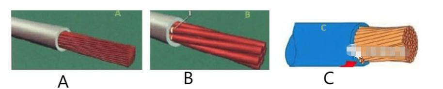
Cutting Wire Peeling
Image A is qualified: the conductor has no scratches, no gaps, and the insulation cuts are straight;
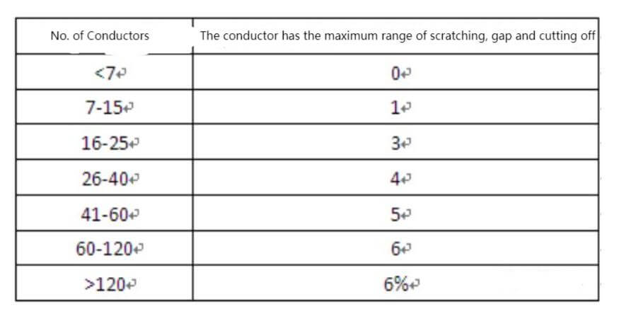
Image B is qualified: the conductor is scratched, but the level does not exceed the requirements of the “Table of Maximum Limits for Conductors Being Scratched or Cut”, and it can be accepted;
Image C is unqualified: The scratch on the conductor exceeds the requirements of the “Table of Maximum Limits for Conductors Scratched or Cut” and is judged to be unqualified.
Terminal Crimping
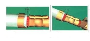
Riveting Inspection:
When inspecting insulation, ensure that it completely surrounds and extends to the riveted sheet.
If the wire is multi-stranded, all wires should pass through the insulating rivet sheet.
The insulation riveting should not cut or damage the insulation in any way.
Furthermore, the insulation riveting should completely cover and support the insulation terminal riveting.
Make sure that the insulation riveting is formed evenly and is tightly connected to the wire without causing any damage to the insulation.
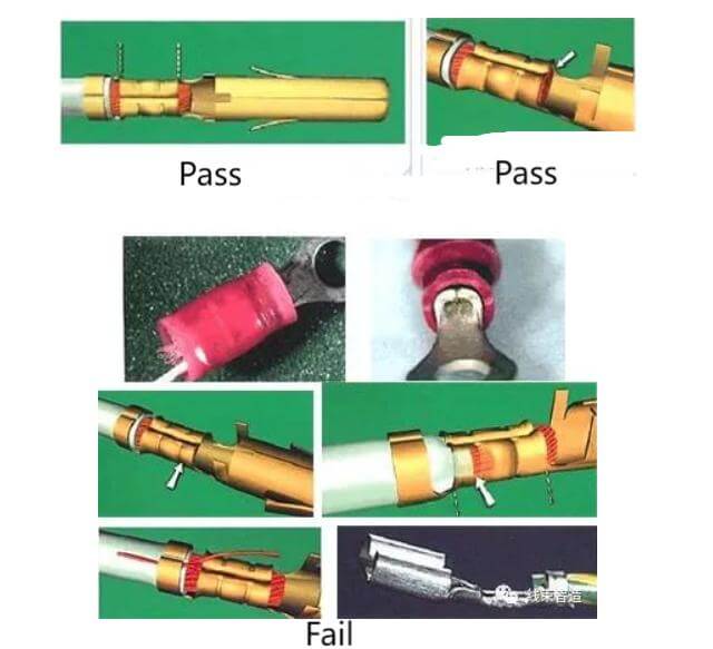
Qualified
During the process of riveting, the insulation surface of the conductor may get slightly deformed, but it should not be cut, damaged or impacted.
The insulation riveting should provide a minimum 180° support to the insulation surface of the conductor and the two tabs should be close to the top of the conductor’s insulation.
The rivet sheet should surround the terminal, but should not close at the top. Instead, it should form an open angle of 45° or closer to the top.
After riveting, the insulating sleeve outside the insulated terminal should be pressed tightly against the terminal.
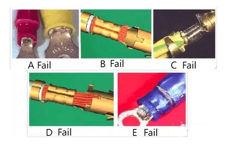
Unqualified:
The riveting sheet pierces the insulation and contacts the conductor (Image A);
Insulation rivets do not provide a minimum 180° of support around the insulation (Image B);
The riveting piece surrounds the top of the conductor, forming an opening angle of >45° (Image C);
The two riveting sheet surround but do not press against the insulation (Image D);
The center conductor is in the insulation riveting area (Image E);
There are strands pressed in the riveting area (Image F)

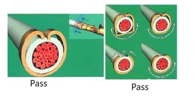
Insulation Inspection
Schematic diagram of the insulation and conductor being qualified in the middle of the inspection window:
Unqualified diagram:
The insulation extends to the conductor riveting area (as shown in Image, the insulation terminal pointed by the arrow is in the riveting area);
The intersection line between the insulation and the conductor is within the insulation riveting range (as shown in Image, the insulation terminal pointed by the arrow is within the riveting area)

Conductor Riveting Inspection
Terminal Bell Mouth Inspection
Key points:
There are bell mouths at both terminals of each conductor rivet area;
The height of the bell mouth is generally 2 times the complete distance to the edge of the conductor the metal thickness of the terminal/connection (as shown in the figure)
Figure C is qualified:
The bell mouth is only present at the terminal (1) where the conductor is inserted, but there is no bell mouth (2) where the conductor of the riveted terminal is flush;
The bell mouth is visible where the conductor enters, but is less than 2 times the thickness of the metal (Figure C)
- Inlet horn pressure port;
- Brush tail horn pressure port (illustrated in Figure C)
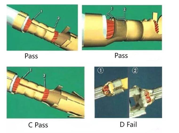
Figure D is not qualified:
There is no bell mouth at the terminal where the conductor is inserted (shown in Figure D ①);
The bell mouth is too large or undersized after riveting (shown in Figure D ②)
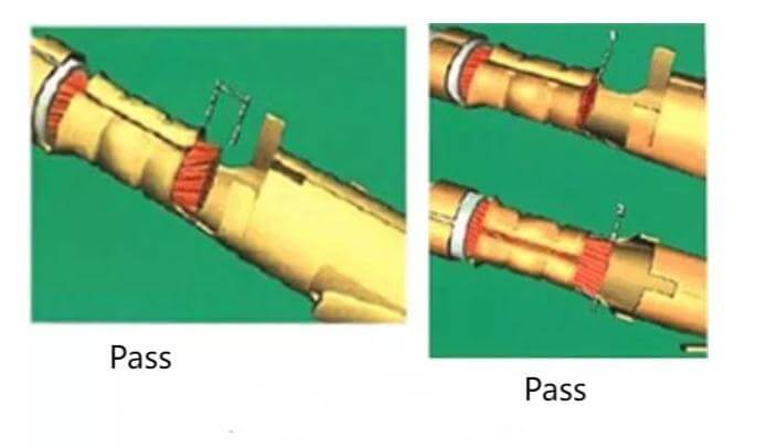
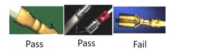
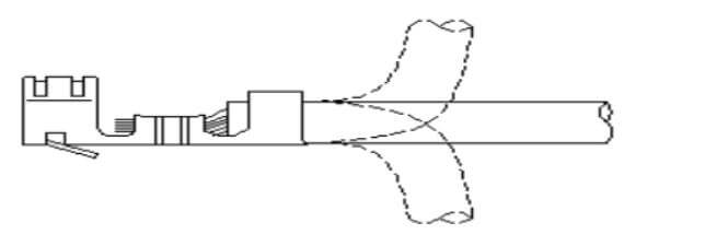
Conductor Brush Inspection
Conductor brush standards:
After the wire passes through the conductor riveting area, there will be a slight protrusion and form a “conductor brush”;
The wires come together flush and do not flare out.
Unqualified:
The end of the wire does not extend flush with the end of the bell (Figure A);
Any conductor strands extend beyond the outer perimeter of the crimp barrel (Figures B and C);
The conductor strands extend into the connector mating area (Figure D, E)
Residual Tape Inspection
Qualified:
There is no damage to the connector or terminal;
Residual tape will not affect the complete connection of the connector terminals;
The length of the residual tape is greater than 2 times the thickness of the terminal material and does not affect assembly (must be improved during the manufacturing process)
Unqualified:
The length of the remaining strip is greater than 2 times its material thickness;
Damage to connections or terminals when removing residual tape;
The remaining piece of material protrudes after the connection is inserted into the connector;
The remaining pieces of material affect the adequate connection with the joint;
No remaining pieces of material and damaged connections/terminals
Terminal Pull Test Standard
Terminal pull test: The terminal pull test is used to evaluate the mechanical integrity of the crimp.
Test frequency: The test interval should be tested once a day before turning on the machine; it is not needed during idle period but should be resumed after restarting; every time the machine is adjusted.
Test method: (According to the wire harness terminal tension operation instructions) According to the wire and terminal tension specifications, use the testing machine in the picture below to conduct the test.
After the insulation is pressed, the conductor needs to be bent 90 degrees up and down three times to check whether the insulation coating is damaged or has slipped out. If there is surface damage or slipping out, the pressing height must be readjusted, as shown in the attached picture

Terminal Crimping Inspection Method
After the insulation is pressed, the conductor needs to be bent 90 degrees up and down three times to check whether the insulation coating is damaged or has slipped out. If there is surface damage or slipping out, the pressing height must be readjusted, as shown in the attached picture
Terminal Appearance Inspection
Whether for wire Harness or cable Harness, The functional end of the terminal must not have openings, deformations, twists or other defects and must ensure that the electrical function is OK.
The terminal coating must not be scratched, yellowed, oxidized or blackened, etc.
If the engineering drawings stipulate special customer requirements, the engineering drawings shall prevail.
Handsome custom wiring harness and industrial cable harness, contact us now, [email protected]